
VIGO PHOTONICS · SMART TAIWAN
Infrared detector and module selection guide
Compare detectors, modules and epitaxial structures by wavelength, bandwidth and integration requirements. SMART Taiwan coordinates technical requirements and supply enquiries with the manufacturer.
Infrared detector selection guide: narrow the choice in four steps
You do not need to know a manufacturer or part number first. Start with the signal you need to measure, then use the comparison and product pages to check the configuration.
Start with wavelength: measurement target and light source
Specify the operating wavelength, light source or absorption line, rather than only the gas name. The table uses a 10% response definition for spectral range; sensitivity is not uniform across that range. Check the response curve, window, optical spot and field of view. An anti-fringing design band is a separate specification.
Choose cooling: chip temperature and ambient are different
Uncooled, 1TE, 3TE and 4TE describe different thermoelectric cooling configurations, not system accuracy levels. Check operating temperature and heat load, then the controller, heat sink and power supply. A module with an integrated TEC controller still needs suitable external heat dissipation.
Check speed: DC, modulated signals or pulses
For steady or slowly varying signals, check DC support first. For example, 32EM-5-01 specifies DC–400 kHz; 32MM-5 is AC-coupled with a 1 Hz–1 MHz band. A bare detector time constant τ and an amplified module bandwidth describe different parts of the signal chain; do not rank them directly or treat them as complete-system speed.
Match the readout: signal type before connector type
TO8 detectors need a suitable front-end amplifier and cooling support. AM / AMS modules provide differential analogue outputs; array modules need matching multi-channel analogue acquisition. Board-to-board and Molex identify physical / electrical connections, not USB, digital data or plug-and-play operation. ADC sampling rate is not the bandwidth listed here.
Not sure yet? Send your known wavelength, source / modulation, number of channels, readout equipment and ambient conditions. Unknown requirements can be clarified with SMART and the manufacturer.
Compare wavelength, cooling, speed and readout
All speeds are typical manufacturer values for the stated configuration. Bare detector time constants and module bandwidths are deliberately labelled separately.
| Model | Typical spectral range | Area / arrangement | Cooling / integration | Speed and load conditions | Electrical readout / connection |
|---|---|---|---|---|---|
| PVIA-4TE-4 | ≤2.0–4.7 μm | 1 × 1 mm optical | 4TE; chip ≈200 K; external TEC controller | Time constant τ: 30 ns typical [1] | TO8 pins; detector current signal, requiring external front-end amplification and readout |
| PVA-3TE-5-AF1x1AR-TO8-wAl2O3AR-70 | 1.64–5.8 μm | 1 × 1 mm active | 3TE; chip ≈210 K; external TEC controller | Time constant τ: 124 ns typical [2] | TO8 pins; external front end and readout. Anti-fringing design band: 1.4–4.0 μm |
| PVIA-4TE-10 | 1.8–11.3 μm | 1 × 1 mm optical | 4TE; chip ≈200 K; external TEC controller | Time constant τ: 3 ns typical [3] | TO8 pins; detector current signal, requiring external front-end amplification and readout |
| 32EM-5-01 | 2.0–5.6 μm | 32 × linear | 3TE; chip ≈230 K; external TEC controller | Bandwidth: DC–400 kHz; Rload = 1 MΩ [4] | 32-channel transimpedance amplification, analogue voltage outputs; 40-pin butterfly package |
| 32MM-5 | 1.7–5.7 μm | 32; 6 × 6 minus corners | 3TE; chip ≈230 K; integrated TEC controller | Bandwidth: 1 Hz–1 MHz; AC-coupled; Rload = 1 MΩ per channel [5] | 32-channel transimpedance amplification, analogue voltage outputs; Molex 87831-5019 connector |
| AMS3140-01 | 2.0–5.5 μm (Tchip −20°C) | 1 × 1 mm | 1TE; chip −20°C; amplifier + TEC controller | Bandwidth: DC–4.0 MHz; Rload = 50 Ω [6] | Differential analogue voltage output; board-to-board connection, external receiver / acquisition circuit required |
| AM03100-02 | 1.7–5.9 μm (Tamb 20°C) | 1 × 1 mm | No TEC; ambient 20°C; differential amplifier | Bandwidth: DC–3.0 MHz; Rload = 1 MΩ [7] | Differential analogue voltage output; 10 × 10 mm PCB with 12 solder pads |
| AMS6140-01 | 2.2–6.8 μm (Tchip −20°C) | 1 × 1 mm | 1TE; chip −20°C; amplifier + TEC controller | Bandwidth: DC–2.6 MHz; Rload = 50 Ω [8] | Differential analogue voltage output; board-to-board connection, external receiver / acquisition circuit required |
| AMIS8140-01 | 1.9–11.0 μm (Tchip −20°C) | 1 × 1 mm | 1TE; chip −20°C; amplifier + TEC controller | Bandwidth: DC–3.0 MHz; Rload = 50 Ω [9] | Differential analogue voltage output; board-to-board connection, external receiver / acquisition circuit required |
Conditions: the first five rows use ambient ≈293 K; the three bare detectors use zero bias. The last four use ambient 20°C: AMS3140-01, AMS6140-01 and AMIS8140-01 are shown at chip −20°C and 3.3 V; AM03100-02 is uncooled at 3.0 V. Rload is the specified output load. Other chip temperatures or loads can change response and bandwidth; consult the source tables below. All TE-cooled configurations need suitable heat dissipation.
Selection aid, not a system performance guarantee. Preliminary documents may change. Spectral coverage and bandwidth alone do not establish gas detection limits, measurement accuracy, camera imaging performance or compatibility with a particular ADC.
Manufacturer sources and revision conditions
Verified on 18 November 2026. Page references identify the principal specification table; read the full document for features, pinout and operating limits.
- PVIA-4TE-4 — V1.0 · 2025-02-11 · Preliminary · p. 1 · Original manufacturer PDF ↗ · Website copy ↗
- PVA-3TE-5-AF1x1AR-TO8-wAl2O3AR-70 — V1.0 · 2025-11-13 · Preliminary · p. 1 · Original manufacturer PDF ↗ · Website copy ↗
- PVIA-4TE-10 — V8.0 · 2025-09-03 · Preliminary · p. 1 · Original manufacturer PDF ↗ · Website copy ↗
- 32EM-5-01 — V2.0 · 2025-06-02 · Preliminary · p. 1 · Original manufacturer PDF ↗ · Website copy ↗
- 32MM-5 — V1.0 · 2025-06-18 · Preliminary · p. 1 · Original manufacturer PDF ↗ · Website copy ↗
- AMS3140-01 — V14.0 · 2026-08-24 · p. 3 · Original manufacturer PDF ↗ · Website copy ↗
- AM03100-02 — V2.0 · 2025-02-05 · Preliminary · p. 3 · Original manufacturer PDF ↗ · Website copy ↗
- AMS6140-01 — V14.0 · 2026-07-08 · Preliminary · p. 3 · Original manufacturer PDF ↗ · Website copy ↗
- AMIS8140-01 — V2.0 · 2026-07-08 · Preliminary · p. 3 · Original manufacturer PDF ↗ · Website copy ↗
Models and configurations
Confirm the operating wavelength and full ordering code. Window, package and cooling configurations can differ within a family.
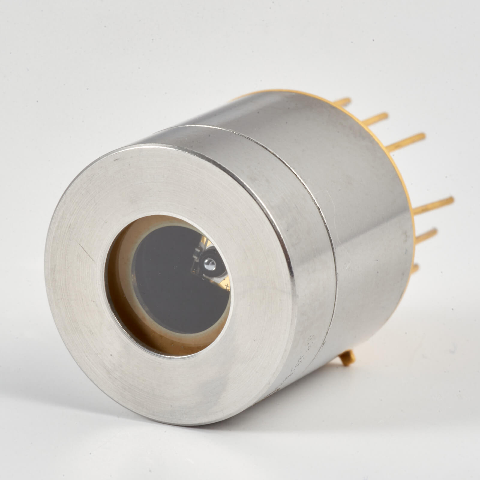
PVIA-4TE-4 infrared detector
Gas analysis, laser spectroscopy and mid-infrared measurements, subject to absorption band and system configuration.
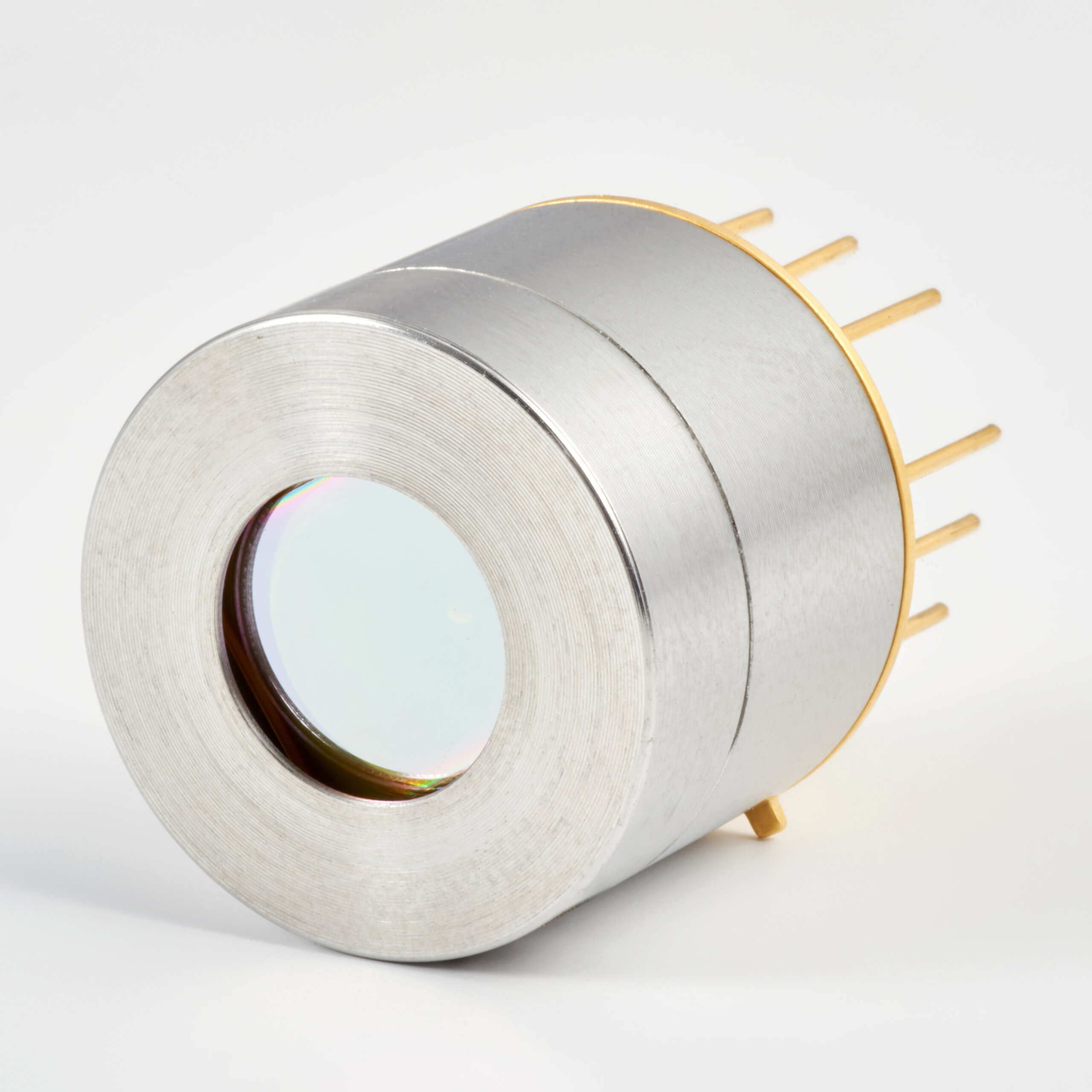
PVA-3TE-5 AF anti-fringing IR detector
Tunable-laser gas spectroscopy and laser control, selected by spectral line, signal bandwidth and optical configuration.
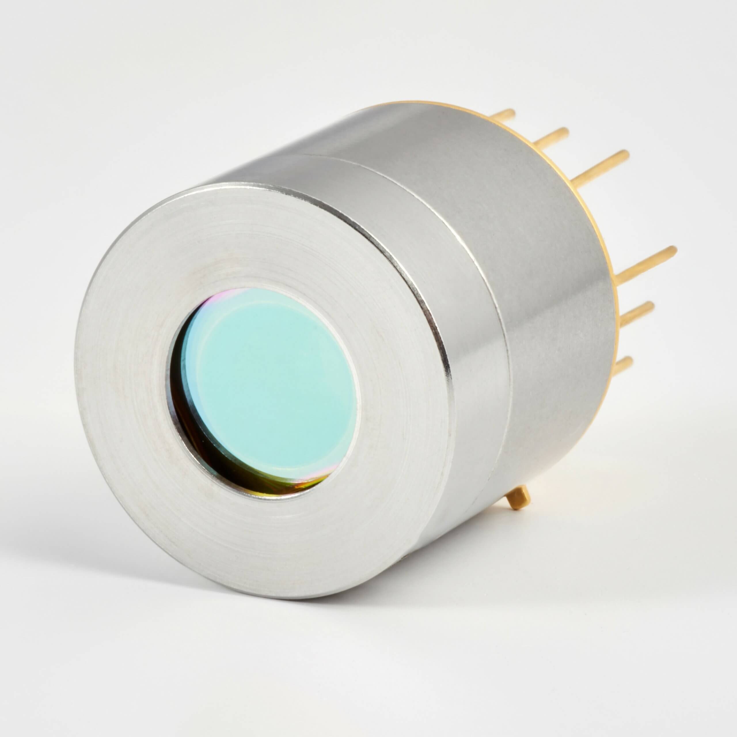
PVIA-4TE-10 infrared detector
FTIR, longer-wavelength spectroscopy and CO₂ laser measurements within the documented optical-power and linearity limits.
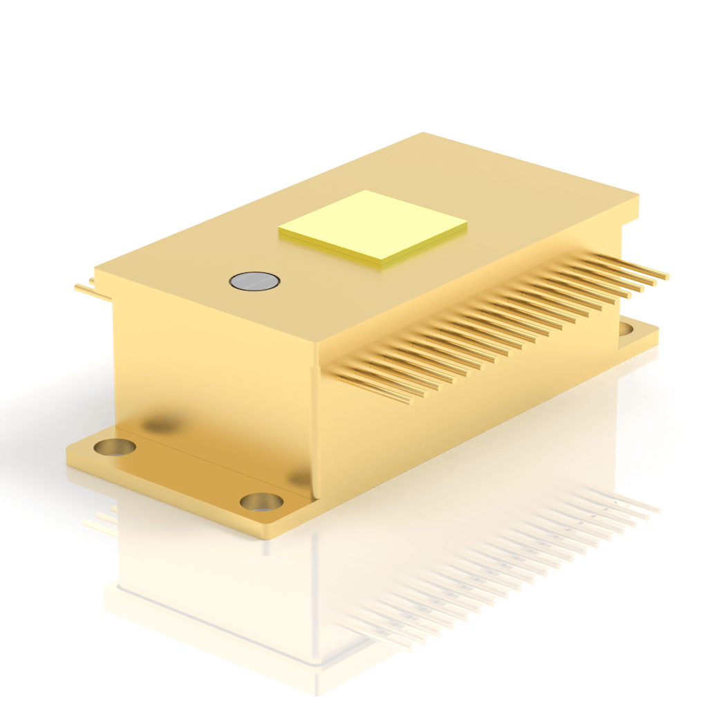
32EM-5-01 32-channel HgCdTe MWIR module
Multi-point temperature monitoring, spectroscopy and multi-channel gas-measurement development with suitable optics, readout and calibration.
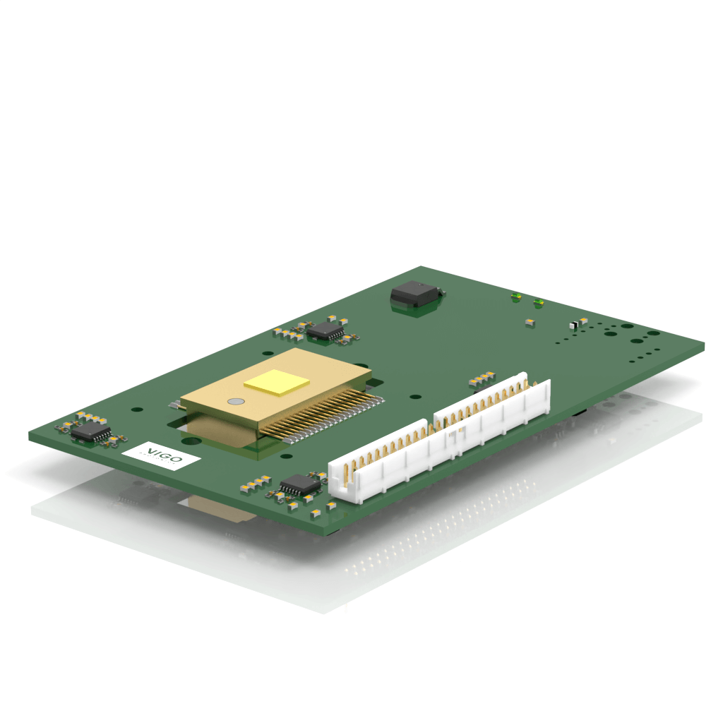
32MM-5 32-channel InAsSb MWIR module
Multi-point MWIR sensing, spectroscopy and gas-analysis development, selected by element geometry, bandwidth and readout requirements.

VIGO III-V epitaxial wafers and photonic structures
Photodetector, VCSEL, QCL and other III-V photonic-device development.
AM / AMS easy-adaptable infrared modules
Compare spectral band, cooling, analogue output and interfaces, with original English documents for each model.
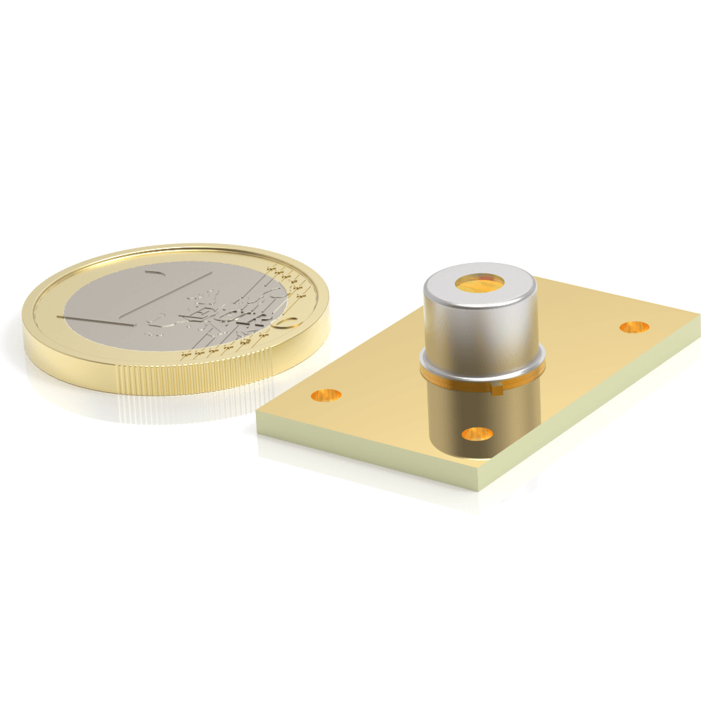
AMS3140-01 infrared detection module
2.0–5.5 μm at Tchip −20°C, with 1TE temperature control, differential amplification, 3.3 V supply and a board-to-board interface.
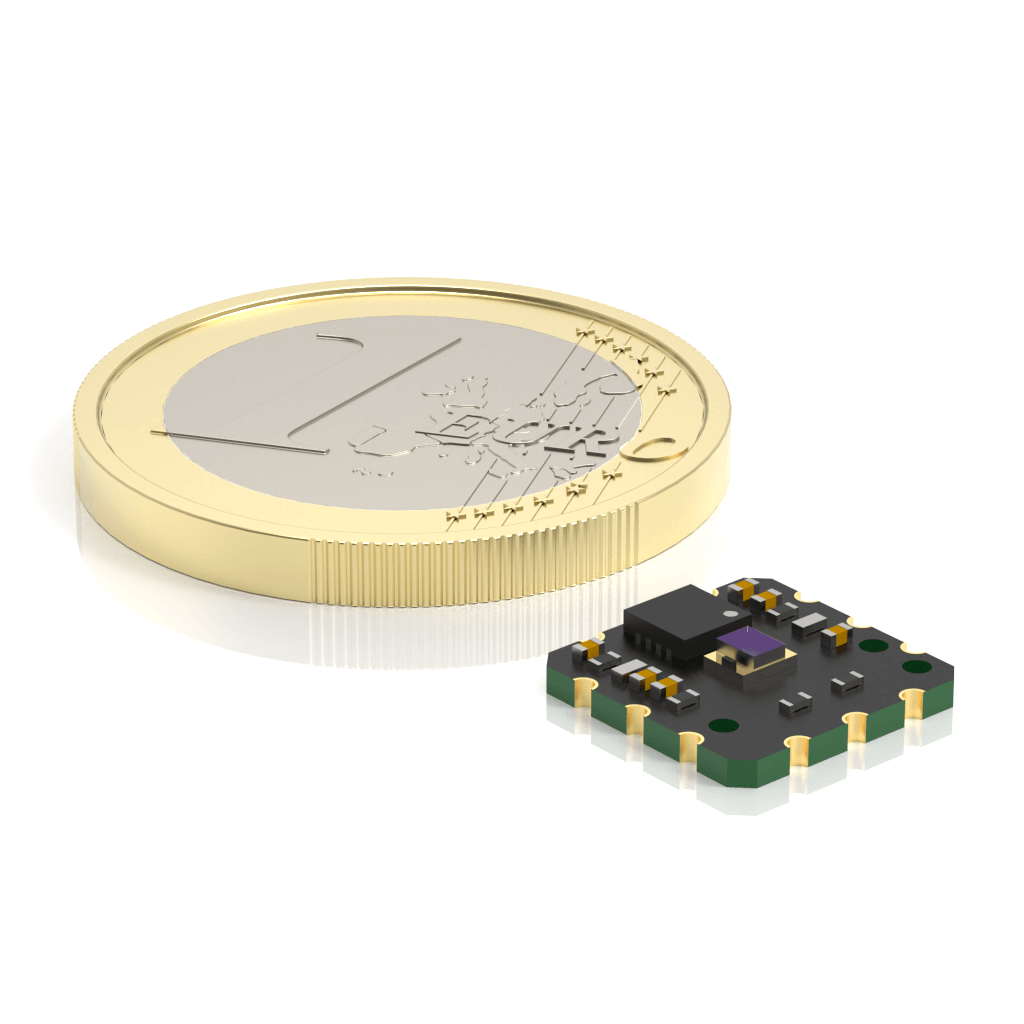
AM03100-02 infrared detection module
1.7–5.9 μm at Tamb 20°C. An uncooled differential-amplifier module with a specified 3.0 V operating point and a 10 × 10 mm solderable PCB.
AMS6140-01 infrared detection module
2.2–6.8 μm at Tchip −20°C, with 1TE control, differential amplification and a 3.3 V supply for longer mid-infrared wavelengths.
AMIS8140-01 optically immersed IR detection module
1.9–11.0 μm at Tchip −20°C. Optical immersion, 1TE control and differential amplification for evaluating signals extending into long-wave infrared.
Start with the application
Infrared detectors for gas analysis and spectroscopy
Begin with the absorption band, source and signal chain. Tunable-laser methods, FTIR and broadband measurements require different selection criteria. SMART helps define detector, amplifier and temperature-control requirements for manufacturer review.
Industrial infrared monitoring and multi-point sensing
Define the spectral band, field of view, response speed and environment for process monitoring, non-contact temperature measurements or multi-point optical sensing. Evaluate the complete measurement chain rather than a single sensitivity figure.
Infrared sensing evaluation for UAV and mobile platforms
For engineering teams evaluating infrared components, modules and readout configurations on mobile platforms. Define the sensing target, working distance, optics and platform resources before selecting a detector direction.
Infrared components for security and monitoring
For development work involving background radiation, fast optical signals and multi-channel readout. Define measurable optical and environmental requirements before evaluating MWIR detectors and integration components.
Original English datasheets
Epitaxial-wafer specifications are agreed per structure; see the manufacturer material-platform information. Manufacturer epi-wafer information ↗
How SMART supports your project
- Define the task: establish the target, wavelength, bandwidth and environment.
- Evaluate the configuration: review the detector, amplifier, TEC, readout and drawings.
- Coordinate with VIGO: clarify technical questions, evaluation options, quotations and lead times.
Optics, mechanics, software and complete-system integration require an agreed project scope; component data does not replace system validation.
Other product families and evaluation options
AM / SMD
InAsSb easy-adaptable modules: select the full model by spectral response, cooling and output requirements.
DevKit / evaluation
Discuss a detector, amplifier, TEC and readout evaluation setup. Tool compatibility and available versions are confirmed with VIGO.
MWIR FPA
Focal-plane arrays require separate pixel, format, optical and readout specifications; a 32-channel module does not establish imaging compatibility.