
VIGO PHOTONICS · SMART TAIWAN
VIGO AM / AMS infrared sensing module selection
Compare VIGO AM03100-02, AMS3140-01, AMS6140-01 and AMIS8140-01 modules by wavelength, bandwidth, cooling and analog readout for gas analysis, spectroscopy and OEM optical integration.
VIGO · SIGNAL PATH
From infrared light to an electrical signal
An AMS3140-01 example showing the roles of optical input, processing inside the module and external readout.
- 01 · OPTICAL INPUT
Incident infrared light
An optical path couples infrared light in the target band to the detector.
Optical coupling is application-dependent - 02 · VIGO MODULE
Detection & amplification
The AMS3140-01 converts incident infrared light into an electrical signal and amplifies it inside the module.
Integrated temperature control; differential analog output - 03 · EXTERNAL SYSTEM
Readout & acquisition
External measurement equipment or a suitable ADC reads the signal. Interface and sampling requirements depend on the system.
External readout is not included in this module
Conceptual signal path, not a wiring diagram. Confirm power, thermal design and readout interfaces against the manufacturer’s documentation.
Full signal path shown.
Choosing an infrared sensing module: three practical questions
What is the difference between a detector and a detection module?
A detector converts incident infrared light into an electrical signal. A module adds amplification and connection interfaces; some models also integrate temperature control. This guide covers VIGO photonic detection modules for industrial spectroscopy and OEM optical systems, where both optical input and electrical readout need to be specified.
Does a module directly report gas concentration?
These four modules convert incident infrared light to analog electrical signals; they do not directly report gas concentration. A gas measurement also needs a suitable source, filtering or tuning method, optical path, receiver or ADC, processing and calibration. Review the selection conditions for NDIR, TDLAS and FTIR before choosing a module.
How can I start without an exact part number?
Share the application, source or wavelength, signal bandwidth or modulation frequency, and intended readout. Include optical power, ambient conditions, quantity and schedule where known. You do not need a complete specification to start; SMART can help organize the questions for manufacturer review.
Selection references: the original VIGO InAsSb AM0 / AMS family data and the individual English datasheets below. Supply, accessories and operating conditions require confirmation.
Compare spectral coverage and integration
| Model | Typical spectral range | Typical bandwidth | Temperature control / integration | Supply |
|---|---|---|---|---|
| AMS3140-01 | 2.0–5.5 μm | DC–4.0 MHz | 1TE; amplifier and controller | 3.3 V |
| AM03100-02 | 1.7–5.9 μm | DC–3.0 MHz | Uncooled; differential amplifier | 3.0 V |
| AMS6140-01 | 2.2–6.8 μm | DC–2.6 MHz | 1TE; amplifier and controller | 3.3 V |
| AMIS8140-01 | 1.9–11.0 μm | DC–3.0 MHz | 1TE; amplifier and controller | 3.3 V |
Typical conditions: Tamb 20°C; Tchip −20°C and 50 Ω bandwidth-test load for the three temperature-controlled modules. AM03100-02 is uncooled. Refer to each original English datasheet for full conditions, the 20°C chip operating point and limits.
Evaluating the AMS3140-01: readout and stability checks
- Verify module and evaluation-board supplies, pinouts and output configurations separately.
- Record differential or single-ended readout, load and gain. Board-level output is not the bare module response.
- Allow temperature stabilization and verify heatsinking before interpreting signals. Check compatibility separately for other AM/AMS models.
Reference: manufacturer AM Evaluation Kit manual (public 2022 version, marked Sample Product). Confirm current module and board documentation when ordering.
Model specifications and documents
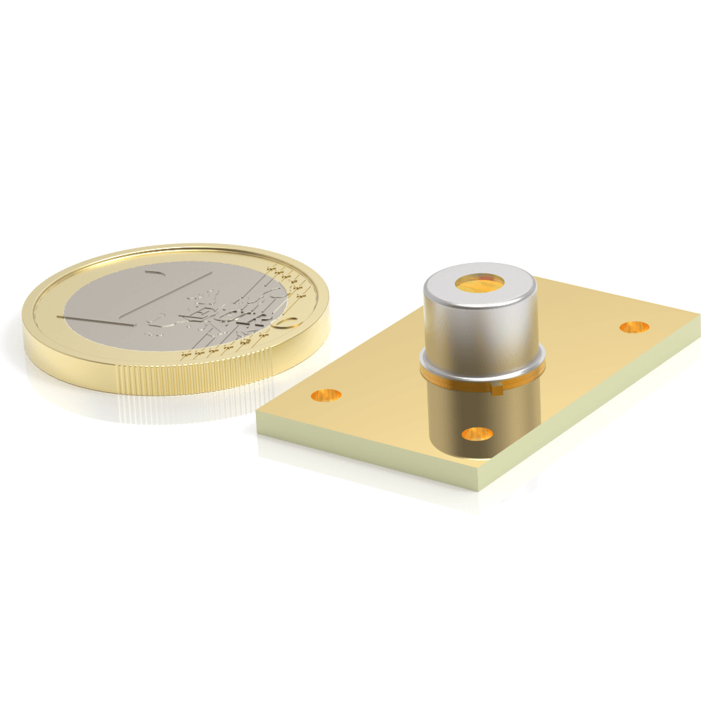
AMS3140-01 infrared detection module
2.0–5.5 μm at Tchip −20°C, with 1TE temperature control, differential amplification, 3.3 V supply and a board-to-board interface.
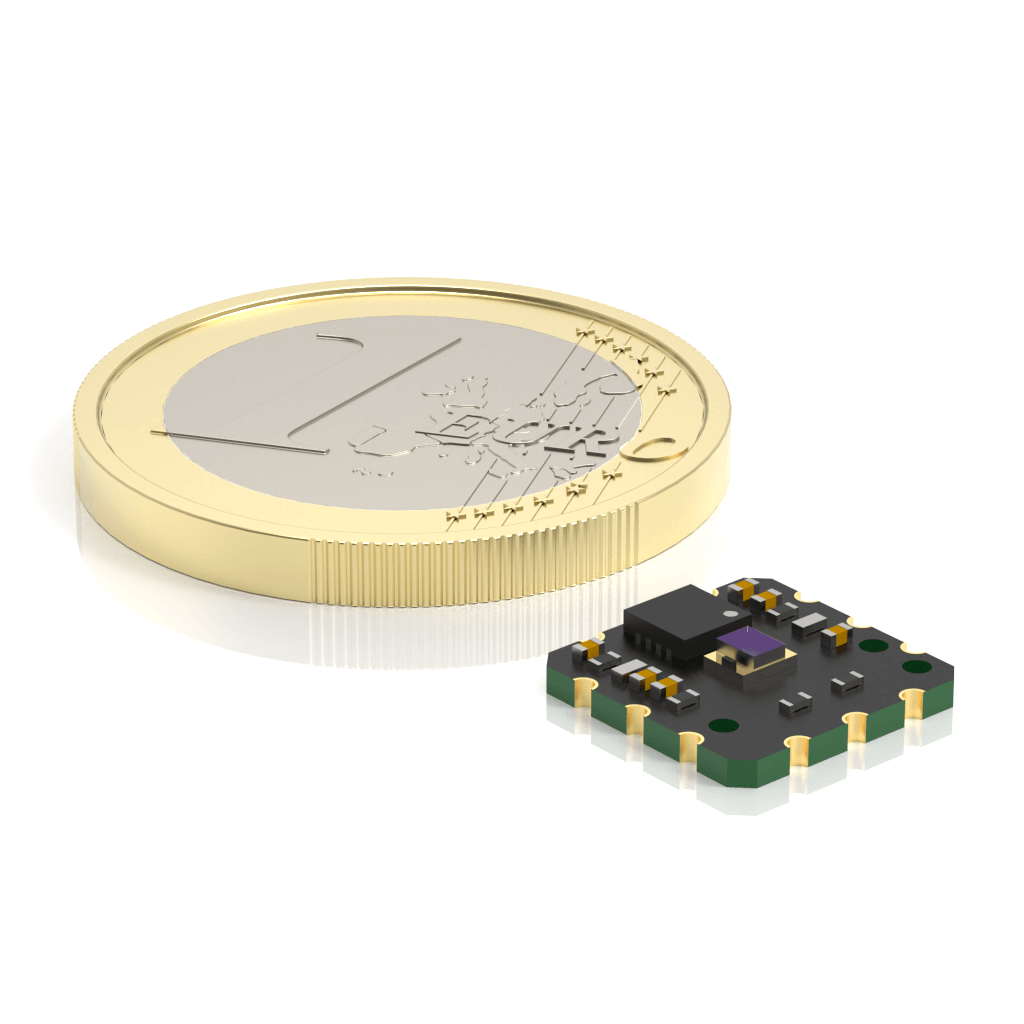
AM03100-02 infrared detection module
1.7–5.9 μm at Tamb 20°C. An uncooled differential-amplifier module with a specified 3.0 V operating point and a 10 × 10 mm solderable PCB.
AMS6140-01 infrared detection module
2.2–6.8 μm at Tchip −20°C, with 1TE control, differential amplification and a 3.3 V supply for longer mid-infrared wavelengths.
AMIS8140-01 optically immersed IR detection module
1.9–11.0 μm at Tchip −20°C. Optical immersion, 1TE control and differential amplification for evaluating signals extending into long-wave infrared.
Choose an integration starting point
- AM03100-02: uncooled solderable PCB; assess ambient-temperature effects, assembly and calibration.
- AMS3140-01 / AMS6140-01: integrated amplification and temperature control; compare operating wavelength, speed and heatsinking.
- AMIS8140-01: optically immersed, longer-wavelength configuration; check beam size, acceptance angle and response at the actual wavelength.
- All four are analogue detection modules requiring optics, receiver / ADC and processing; they are not USB sensors or complete gas analysers.
Module integration and qualification
- Source / measurement target
- Filters and optical coupling
- IR detection module
- Differential receiver / ADC
- Signal processing and calibration
The module provides part of the sensing and analogue chain. A complete measurement also needs optics, power, readout and calibration.
Start with the measurement task, wavelength or source, modulation frequency, optical power, quantity and schedule. A fixed model is not required to begin the discussion.
Original English documents
Discuss the configuration for your application
SMART coordinates candidate models, supporting components, manufacturer technical questions, quotations and lead time.
Submit a module inquiry