
VIGO PHOTONICS · SMART TAIWAN
AMS3140-01 mid-infrared gas sensing module
AMS3140-01
For mid-infrared gas sensing that needs a single analogue channel with amplification and temperature control, evaluate AMS3140-01. Match the source and absorption band before defining the receiver and thermal design.
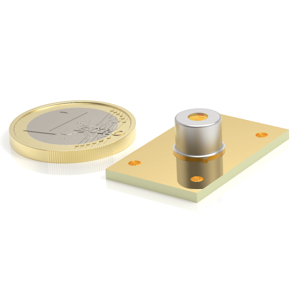
Specifications and configuration
| Material / detection | InAsSb / photovoltaic |
|---|---|
| Active / optical area | 1 × 1 mm (active area) |
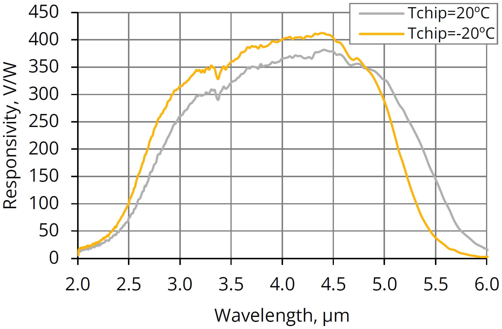
| Typical spectral range | 2.0–5.5 μm (Tchip −20°C) |
| Peak wavelength | 4.0 μm (typ.) |
| Typical responsivity | 400 V/W (λpeak) |
| Typical D* | 2.0 × 10⁹ cm·Hz½/W (λpeak, 1 kHz) |
| Typical bandwidth | DC–4.0 MHz (Rload 50 Ω) |
| Supply | 3.3 V |
| Signal output | Differential analogue output |
| Cooling / temperature control | 1TE; integrated controller |
| Outline / interface | 30 × 19 × 10 mm; board-to-board connector |
Tamb = 20°C; Tchip = −20°C; +3.3 V; Rload = 1 MΩ to ground unless noted; fhi at Rload = 50 Ω.
Typical values are not guaranteed limits. Refer to the original English datasheet for full test conditions, minimum / maximum values and operating limits. D* figures measured at different frequencies are not directly comparable.
Manufacturer spectral response
Temperature and readout conditions
| Tchip | Spectral range (10%) | Peak responsivity | High cut-off frequency |
|---|---|---|---|
| −20°C | 2.0–5.5 μm | 400 V/W | 4.0 MHz |
| 20°C | 2.0–5.9 μm | 360 V/W | 3.0 MHz |
Tamb = 20°C; high cut-off frequency measured at Rload = 50 Ω. Temperature control and heatsinking determine the achievable operating point.
Configuration checks before evaluation
- Choose the chip operating point under the datasheet conditions; the integrated controller does not remove the need for heat dissipation.
- Match the differential output to receiver / ADC load and input range; it is not a USB or digital-data interface.
- Validate gas concentration performance with the source, optical path and calibration, not detector D* alone.
Original English documents and resources
V14.0 · 2026-08-24
Application guidance checked on 18 November 2026 against the manufacturer product page and linked datasheet. Candidate applications remain subject to the complete optical and readout design.
Start with your measurement requirements
Share the model or application, wavelength, signal bandwidth, quantity and desired schedule. Unknown items can be discussed during selection.
Submit a VIGO inquiry